Tobias Bonwetsch
Sebastian Gmelin
Bergit Hillner
Bart Mermans
Jan Przerwa
Arno Schlueter
Rafael Schmidt
| generating construction drawings |

|

|
|
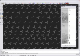
The geometry is imported into the commercial CAD-Software “Rhinoceros”. An especially programmed parser interprets the data of the model now closer defined by the set of construction parameters and creates the physical elements to be produced. First, the geometric data is rebuilt, following, the actual construction data is calculated and visualized. The polygonal cell elements are offsets of the cell edges, customized by selecting inner and outer radii as well as edge curvature.
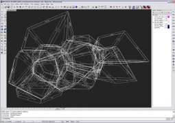
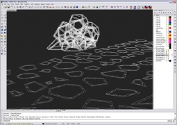
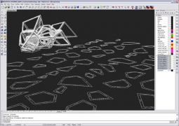
The scripts automatically create and arrange the necessary cutting plans for the machines. Each polygonal element, a so called “frame”, is rotated into an even plane, necessary milling offsets for the machine paths are automatically calculated and added. A second procedure builds up the geometry for the frame connectors. It also generates the cutting plans needed for the production of the several hundred individual frame connectors, each one shaped in an individual angle derived by the geometry of the overall structure.
left image variant 1, right image variant n
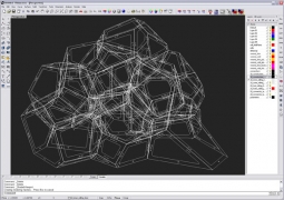 
rhino : step cd 1 > generate construction model
rhino : step cd 2 > rotate shapes into even plane
 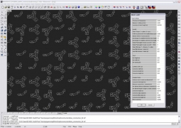
rhino : step cd 3 > generate connectorsrotate shapes into even plane
igs export
10,0,13H050927.225412; G 12 314 1 0 0 0 0 0 000000200D 1 314 0 2 1 0 0 0 COLOR 0D 2 314 2 0 0 0 0 0 000000200D 3 314 0 1 1 0 0 0 COLOR 0D 4 314 3 0 0 0 0 0 000000200D 5 314 0 4 1 0 0 0 COLOR 0D 6 406 4 0 0 2 0 0 000000300D 7 406 0 -1 1 3 0 0LEVELDEF 0D 8 406 5 0 0 3 0 0 000000300D 9 406 0 -1 1 3 0 0LEVELDEF 0D 10 406 6 0 0 4 0 0 000000300D 11 406 0 -3 1 3 0 0LEVELDEF 0D 12 406 7 0 0 5 0 0 000000300D 13 406 0 -5 1 3 0 0LEVELDEF 0D 14 126 8 0 0 4 0 0 000000000D 15 126 0 -3 8 0 0 03d BsCrv 0D 16 126 16 0 0 4 0 0 000000000D 17 126 0 -3 6 0 0 03d BsCrv 0D 18 110 22 0 0 4 0 0 000000000D 19 110 0 -3 3 0 0 0 3d Line 0D 20 126 25 0 0 4 0 0 000000000D 21 126 0 -3 8 0 0 03d BsCrv 0D 22 126 33 0 0 4 0 0 000000000D 23 126 0 -3 8 0 0 03d BsCrv 0D 24 126 41 0 0 4 0 0 000000000D 25 126 0 -3 8 0 0 03d BsCrv 0D 26 126 49 0 0 4 0 0 000000000D 27 126 0 -3 11 0 0 03d BsCrv 0D 28 110 60 0 0 4 0 0 000000000D 29 110 0 -3 3 0 0 0 3d Line 0D 30 126 63 0 0 4 0 0 000000000D 31 126 0 -3 8 0 0 03d BsCrv 0D 32 126 71 0 0 4 0 0 000000000D 33 126 0 -3 11 0 0 03d BsCrv 0D 34 110 82 0 0 4 0 0 000000000D 35 110 0 -3 3 0 0 0 3d Line 0D 36 126 85 0 0 4 0 0 000000000D 37 126 0 -3 6 0 0 03d BsCrv 0D 38 126 91 0 0 4 0 0 000000000D 39 126 0 -3 8 0 0 03d BsCrv 0D 40 110 99 0 0 2 0 0 000000000D 41 110 0 -1 3 0 0 0 3d Line 0D 42 124 102 0 0 0 0 0 000000000D 43 124 0 0 4 0 0 0 0D 44 100 106 0 0 2 0 43 000000000D 45 100 0 -1 2 0 0 0 3d Arc 0D 46 110 108 0 0 2 0 0 000000000D 47 110 0 -1 3 0 0 0 3d Line 0D 48 110 111 0 0 3 0 0 000000000D 49 110 0 -1 3 0 0 0 3d Line 0D 50 124 114 0 0 0 0 0 000000000D 51 124 0 0 4 0 0 0 0D 52 100 118 0 0 3 0 51 000000000D 53 100 0 -1 2 0 0 0 3d Arc 0D 54 110 120 0 0 3 0 0 000000000D 55
import to SurfCam
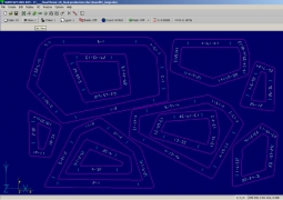
transfer to cnc–machines
CAM cutting plans
material frames: 49.73sqm material connectors: 4,80sqm number of frames: 111 number of connectors: 1368
average milling time for one frame: 8-9 minutes
average laser cutting time for one connector: 70-80 seconds
total milling time: 34 hours hours of assembly: 16 hours |