Tobias Bonwetsch
Sebastian Gmelin
Bergit Hillner
Bart Mermans
Jan Przerwa
Arno Schlueter
Rafael Schmidt
| CNC production |

|

|
|
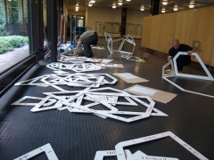
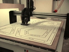
All prototypes were completely manufactured on CNC-machines (CNC = Computer Numerical Controlled). The three-dimensional data models were also used to create smaller prints with the 3D-printer as well as larger prototypes with the 3-axis-CNC-mill and the CNC-laser cutter.
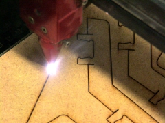
For the production of the frames the milling software “surfcam” was used. In this program the two dimensional cutting lines of the construction plans are transformed into three-dimensional milling paths by adding the thickness of the 0.6 mm thick, coated MDF (medium dense wood fibre) material. Taking to account that the CNC-mill has an imprecision of 0.5 mm to 1.5 mm, more specific information is given to the CNC-mill through an interface, e.g. type of cut, spindle speed and milling tool. With this data the program generates a machine compatible code, the so called “G-code” which can be directly processed.
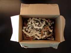
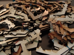
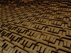
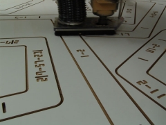
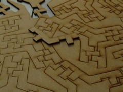
In addition to the milling process all parts are automatically numbered in an especially designed numbering pattern. The pattern clearly labels each of the individual polygonal cell elements as well as each of the several hundred connector elements. Only these labels make the correct erection of the structure possible, otherwise the 1200 final parts could not have been physically “reassembled”. For the production of the frame connectors more precise results were needed, therefore the CNC-laser with an imprecision of only 0.2 mm was used. The MDF material gets “burned” away by the focused laser beam. This way the cutting edges are hardened in order to increase the stability and solidity of the frame connectors made out of only 5 mm MDF (medium dense wood fibre) material. The results of the mock-ups and prototype tests were examined and re-evaluated. They served as basis for optimization and acceleration of the production process as well as for the refinement of the construction parts.
  |